

نام محصول: کابل ماژول دوربین سونی MIPI KEL USL20-30SS-0045-C lvds edp
زمین تماس: زمین 0.4 میلی متر
اتصال: USL20-30SS-0045-C
زمین تماس: گام 0.4 میلی متر
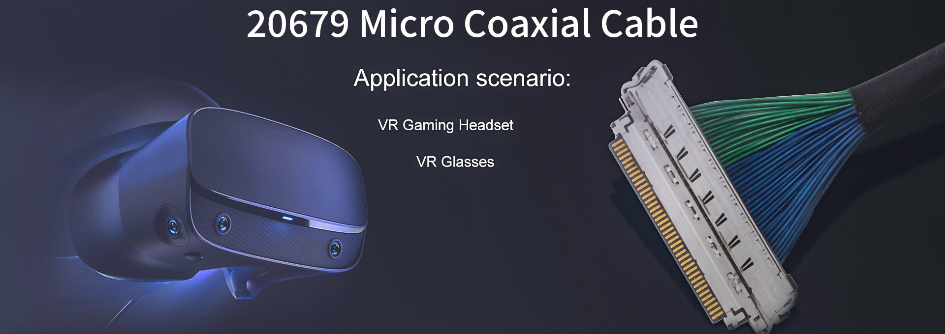
نام محصول: 20788-060T-01 کابل میکرو کواکسیال کابل lvds
ماده: 60 پین
نام محصول: 20453-240t-03 To 20453-240t-03 مونتاژ کابل ال سی دی Edp Lvds
تعداد پین: 40p
زمین تماس: گام 0.5 میلی متر
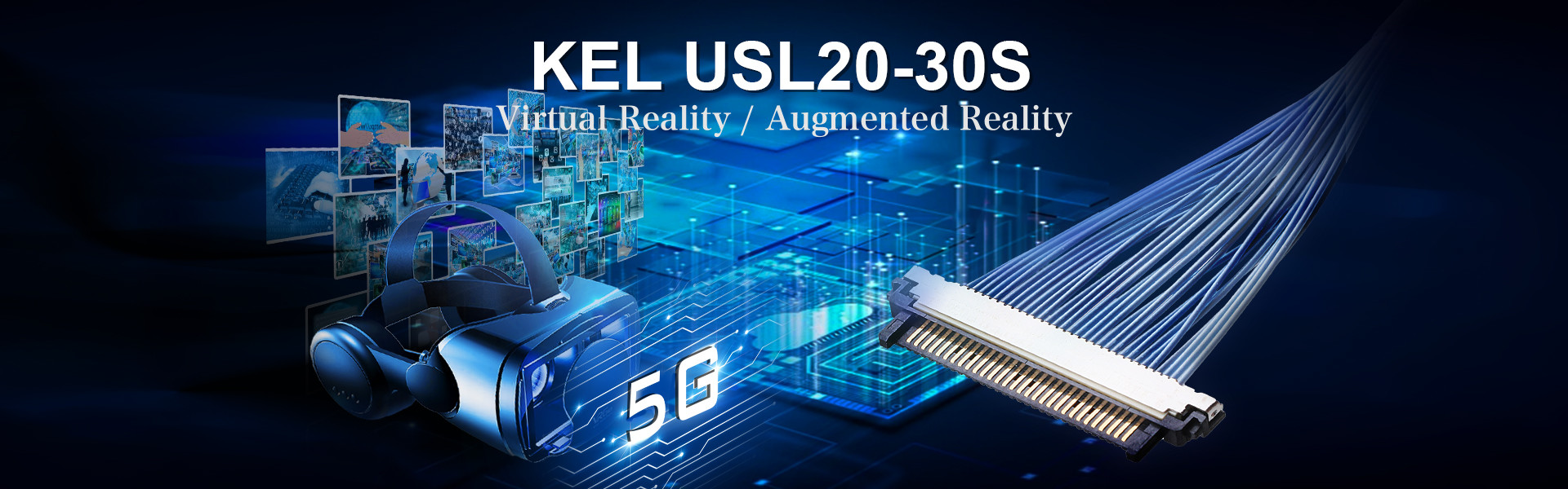
نام محصول: کابل USLS20 30s UslS Series Kel 30 پین کابل میکرو کواکسیال LVDS
کانکتور: USLS20-30SS-01
زمین تماس: گام 0.4 میلی متر


 english
 français
 Deutsch
 Italiano
 Русский
 Español
 português
 Nederlandse
 ελληνικά
 日本語
日本語
 한국
한국
 العربية
 हिन्दी
 Türkçe
 indonesia
 tiếng Việt
 ไทย
ไทย
 বাংলা
বাংলা
 فارسی
فارسی
 polski

